

Grooved Couplings — Rigid & Flexible, 1" to 12"
Ductile iron grooved couplings to ASTM A536 Gr. 65-45-12, UL Listed and FM Approved, in ready stock ex-Delhi. Full dimension tables, bolt torques and the choice between rigid and flexible, from Vijay Sales Corporation.
What a grooved coupling actually does
A coupling has four parts: an upper housing, a lower housing, a gasket and two bolts with nuts. The gasket slips over the gap between two grooved pipe ends. The two housing halves close around the gasket, and a raised key running round the inside face of each half drops into the groove on both pipes. Tightening the bolts pulls the halves together until the pads meet, which compresses the gasket onto the pipe wall and traps the keys in the grooves.
The gasket seals and the housing holds — two separate jobs. The gasket is C-shaped in section, so line pressure acts on the inside of the lip and forces it harder against the pipe. The joint therefore seals better as pressure rises, which is the opposite of a compressed flange gasket that relies on bolt load alone.
Rigid coupling — XGQT 1
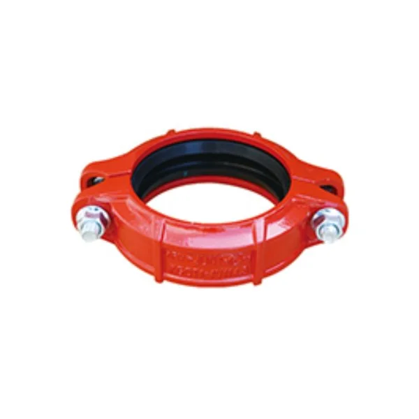
The rigid coupling uses an angled key profile that wedges against both walls of the groove as the bolts come up. Once the pads are metal-to-metal the pipe ends cannot rotate, deflect or draw apart. The joint behaves as a fixed connection, which is what a structural engineer assumes when a riser is designed as a braced line.
Use a rigid coupling for:
- Vertical risers, where the line must carry its own weight without articulating at every joint
- Connections at valves, pumps and equipment, where movement would load the flange or the equipment nozzle
- Runs where the designer has specified a rigid system and hangers are spaced accordingly
- Anywhere a flexible joint would let the line walk under flow-induced thrust
Sizes 1" to 12", 12 sizes. Rigid couplings from Rs. 418 MRP — see the full Sant grooved fittings price list with dealer discount.
Rigid coupling dimensions
XGQT 118 sizes| Nominal size mm / in | Pipe O.D. mm | Working pressure PSI / MPa | Bolt size no. x mm | Φ mm | L mm | H mm |
|---|---|---|---|---|---|---|
| 25 / 1 | 33.7 | 300 / 2.07 | 2-M10*45 | 55.6 | 98 | 44 |
| 32 / 1-1/4 | 42.4 | 300 / 2.07 | 2-M10*45 | 66 | 107 | 44 |
| 40 / 1-1/2 | 48.3 | 300 / 2.07 | 2-M10*45 | 74 | 115 | 44 |
| 50 / 2 | 60.3 | 300 / 2.07 | 2-M10*55 | 88.4 | 125 | 46 |
| 65 / 2-1/2 | 73 | 300 / 2.07 | 2-M10*55 | 102.2 | 140 | 46 |
| 65 / 2-1/2 | 76.1 | 300 / 2.07 | 2-M10*55 | 102.2 | 140 | 46 |
| 80 / 3 | 88.9 | 300 / 2.07 | 2-M10*60 | 117.4 | 154 | 46 |
| 100 / 4 | 108 | 300 / 2.07 | 2-M12*65 | 138.8 | 184 | 48 |
| 100 / 4 | 114.3 | 300 / 2.07 | 2-M12*65 | 146.6 | 190 | 48 |
| 125 / 5 | 133 | 300 / 2.07 | 2-M12*75 | 158 | 212 | 48 |
| 125 / 5 | 139.7 | 300 / 2.07 | 2-M12*75 | 171.2 | 220 | 48 |
| 125 / 5 | 141.3 | 300 / 2.07 | 2-M12*75 | 171.2 | 220 | 48 |
| 150 / 6 | 159 | 300 / 2.07 | 2-M12*75 | 192 | 240 | 48 |
| 150 / 6 | 165.1 | 300 / 2.07 | 2-M12*75 | 196.2 | 244 | 48 |
| 150 / 6 | 168.3 | 300 / 2.07 | 2-M12*75 | 199.4 | 246 | 48 |
| 200 / 8 | 219.1 | 232 / 1.6 | 2-M16*85 | 256.4 | 326 | 58 |
| 250 / 10 | 273 | 232 / 1.6 | 2-M20*100 | 316 | 426 | 64 |
| 300 / 12 | 323.9 | 232 / 1.6 | 2-M22*130 | 380 | 470 | 65 |
Folio 05/06. The catalogue prints the same dimensional table for the rigid (XGQT1) and flexible (XGQT2) coupling; the difference between them is the housing geometry and the amount of angular and axial movement the joint allows, not the envelope size.
Flexible coupling — XGQT 2
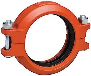
The flexible coupling uses a key that is deliberately narrower than the groove. That clearance is the whole point: it lets the joint rotate through roughly a degree and take up a small amount of linear movement without breaking the seal, because the gasket stays compressed across the whole range of travel.
Use a flexible coupling for:
- Seismic movement — a run of flexible joints absorbs building drift that would crack a welded line
- Thermal expansion on chilled and hot water headers, in place of expansion loops or bellows
- Pump and chiller connections, where the joint isolates vibration instead of transmitting it down the pipe
- Long straight runs, where placing flexible couplings at intervals accommodates the total movement of the line
Sizes 1" to 12", 12 sizes. From Rs. 418 MRP — see rates.
Flexible coupling dimensions
XGQT 218 sizes| Nominal size mm / in | Pipe O.D. mm | Working pressure PSI / MPa | Bolt size no. x mm | Φ mm | L mm | H mm |
|---|---|---|---|---|---|---|
| 25 / 1 | 33.7 | 300 / 2.07 | 2-M10*45 | 55.6 | 98 | 44 |
| 32 / 1-1/4 | 42.4 | 300 / 2.07 | 2-M10*45 | 66 | 107 | 44 |
| 40 / 1-1/2 | 48.3 | 300 / 2.07 | 2-M10*45 | 74 | 115 | 44 |
| 50 / 2 | 60.3 | 300 / 2.07 | 2-M10*55 | 88.4 | 125 | 46 |
| 65 / 2-1/2 | 73 | 300 / 2.07 | 2-M10*55 | 102.2 | 140 | 46 |
| 65 / 2-1/2 | 76.1 | 300 / 2.07 | 2-M10*55 | 102.2 | 140 | 46 |
| 80 / 3 | 88.9 | 300 / 2.07 | 2-M10*60 | 117.4 | 154 | 46 |
| 100 / 4 | 108 | 300 / 2.07 | 2-M12*65 | 138.8 | 184 | 48 |
| 100 / 4 | 114.3 | 300 / 2.07 | 2-M12*65 | 146.6 | 190 | 48 |
| 125 / 5 | 133 | 300 / 2.07 | 2-M12*75 | 158 | 212 | 48 |
| 125 / 5 | 139.7 | 300 / 2.07 | 2-M12*75 | 171.2 | 220 | 48 |
| 125 / 5 | 141.3 | 300 / 2.07 | 2-M12*75 | 171.2 | 220 | 48 |
| 150 / 6 | 159 | 300 / 2.07 | 2-M12*75 | 192 | 240 | 48 |
| 150 / 6 | 165.1 | 300 / 2.07 | 2-M12*75 | 196.2 | 244 | 48 |
| 150 / 6 | 168.3 | 300 / 2.07 | 2-M12*75 | 199.4 | 246 | 48 |
| 200 / 8 | 219.1 | 232 / 1.6 | 2-M16*85 | 256.4 | 326 | 58 |
| 250 / 10 | 273 | 232 / 1.6 | 2-M20*100 | 316 | 426 | 64 |
| 300 / 12 | 323.9 | 232 / 1.6 | 2-M22*130 | 380 | 470 | 65 |
Reducing coupling — XGQT 2B
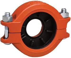
A reducing coupling joins two different pipe sizes directly, using a stepped gasket that seals on both diameters. It saves a separate reducer and a joint, which matters where headroom is tight or a branch has to drop a size immediately off a header.
Available in 11 size combinations from 2" x 1-1/2" to 6" x 4". Where the size step is larger than the reducing coupling range covers, use a concentric reducer (XGQT 07) with a coupling on each end.
Reducing coupling
XGQT 2B11 sizes| Size (inch) | Dim. (mm) | MRP (Rs.) |
|---|---|---|
| 2" x 1-1/2" | 60.3 x 48.3 | Rs. 782 |
| 2-1/2" x 1-1/2" | 76.1 x 48.3 | Rs. 930 |
| 2-1/2" x 2" | 76.1 x 60.3 | Rs. 930 |
| 3" x 1-1/2" | 88.9 x 48.3 | Rs. 1,277 |
| 3" x 2" | 88.9 x 60.3 | Rs. 1,277 |
| 3" x 2-1/2" | 88.9 x 76.1 | Rs. 1,277 |
| 4" x 1-1/2" | 114.3 x 48.3 | Rs. 1,465 |
| 4" x 2" | 114.3 x 60.3 | Rs. 1,465 |
| 4" x 2-1/2" | 114.3 x 76.1 | Rs. 1,465 |
| 4" x 3" | 114.3 x 88.9 | Rs. 1,465 |
| 6" x 4" | 165.1 x 114.3 | Rs. 3,234 |
Rigid or flexible — the decision
| Situation | Coupling | Why |
|---|---|---|
| Vertical riser | Rigid | The line must not articulate under its own weight. |
| Pump or chiller connection | Flexible | Isolates vibration from the pipework. |
| At a valve or equipment flange | Rigid | Stops movement loading the nozzle. |
| Long straight run with temperature swing | Flexible | Takes up expansion joint by joint, replacing loops. |
| Seismic zone | Flexible | Deflects with building drift instead of cracking. |
| Line designed as a braced structure | Rigid | Hanger spacing assumes a rigid joint. |
| Where the pipe may walk under thrust | Rigid | A flexible joint would let the run creep. |
| Buried or backfilled line | Flexible | Absorbs settlement without stressing the pipe. |
Mixing the two on one system is normal and expected. A typical fire riser uses rigid couplings up the shaft and flexible couplings either side of the pump set and at each floor take-off.
Installation
The sequence below is the manufacturer's, from the Sant grooved catalogue. It applies to mechanical tees and to couplings alike.
- Pipe preparationClean the gasket sealing surface within 16 mm of the hole and inspect it for defects that would stop the gasket sealing. Do not drill the hole on a weld line.
- Remove burrsRemove any burrs or slug left at the pipe hole before assembly, to protect the gasket and avoid leakage.
- Gasket installationInsert the gasket into the outlet housing with the gasket tab lined up with the tab recesses in the housing. Align the outlet housing over the pipe hole so that the locating collar sits in the hole.
- AlignmentAlign the strap around the pipe, insert the bolts and run the nuts up finger tight.
- Tighten nutsTighten the nuts alternately and evenly to the specified bolt torque.
- Assembly completedCheck that the gaps between the upper and lower housings are even on both sides.
Bolt torque
Specified bolt torque
ANSI bolts3 sizes| Bolt size (ANSI) | Specified torque lbs-ft | Specified torque N·m |
|---|---|---|
| 3/8 in | 30 – 45 | 40 – 60 |
| 1/2 in | 80 – 100 | 110 – 135 |
| 5/8 in | 100 – 130 | 135 – 175 |
Folio 39/40. The catalogue's caution: over-torquing can damage the bolt or the casting and lead to joint separation; under-torquing lowers pressure retention and bend-load capability and can cause leakage or separation.
Spanner sizes: M10 takes 15 mm, M12 takes 18 mm, M16 takes 24 mm, M20 takes 30 mm, M22 takes 34 mm. Bolts and nuts are made from 40Cr or 35# steel and reach Gr. 8.8 mechanical properties after heat treatment. Only one wrench is needed to make up the joint.
Groove dimensions and tolerances for every size are published on the grooved fittings dimensions and groove specs page. Couplings for fire systems are covered on grooved fittings for fire fighting systems.
Frequently asked questions
What is the difference between a rigid and a flexible grooved coupling?
The housing key profile. A rigid coupling wedges against both groove walls so the joint cannot move; a flexible coupling leaves clearance in the groove so the joint can deflect about a degree and take up linear movement. The gasket, the bolts and the overall envelope are the same on both.
Can I use a flexible coupling everywhere instead of a rigid one?
No. On a riser or at an equipment connection the line needs to be held rigid, and a run made up entirely of flexible couplings can walk under flow-induced thrust or sag between hangers. Use flexible couplings where movement has to be absorbed and rigid couplings everywhere else.
What does a grooved coupling cost?
Rigid couplings start at Rs. 418 MRP for the 1" size and rise with diameter. All 35 coupling sizes across rigid, flexible and reducing types are listed on the Sant grooved fittings price list with dealer discount.
What bolt torque should I use?
The catalogue specifies 30 to 45 lbs-ft (40 to 60 N·m) for 3/8 inch bolts, 80 to 100 lbs-ft (110 to 135 N·m) for 1/2 inch, and 100 to 130 lbs-ft (135 to 175 N·m) for 5/8 inch. Tighten the nuts alternately and evenly, and check that the gaps between the two housings are even on both sides when you finish.
What sizes are grooved couplings available in?
Rigid and flexible couplings run 1" to 12". Reducing couplings cover 11 size combinations from 2" x 1-1/2" up to 6" x 4". Ready stock is held in Delhi for the moving sizes.
Need couplings off the shelf?
Send the sizes and quantities. Stock position and net rates come back the same working day.