

Grooved Fittings for Fire Fighting Systems — UL Listed & FM Approved
Ductile iron grooved couplings, elbows, tees, mechanical tees and flange adaptors for sprinkler mains, hydrant risers and pump manifolds. Ready stock ex-Delhi from Vijay Sales Corporation, with project BOQs priced the same working day.
Why fire contractors specify grooved
No hot work permit
Welding inside an occupied building means a hot-work permit, a fire watch, and in many premises a shutdown of the very detection system being extended. A grooved joint involves no flame at all, so a sprinkler main can be extended over a working floor without any of that.
Faster sprinkler installation
A fitter cuts, grooves and bolts up a joint in a couple of minutes with one wrench. On a repetitive job — floor after floor of branch lines and drops — that difference against welding compounds into weeks of programme.
Seismic movement is absorbed
Flexible couplings deflect at every joint, so a run takes up building drift instead of concentrating stress at a weld. This is the same property that has made grooved piping standard on seismic-zone fire systems.
Maintenance and retrofit
Any joint opens with a spanner. Replacing a valve, adding a floor take-off or reconfiguring a head layout means unbolting a coupling rather than cutting into a charged system.
Mechanical tees for drops
A hole is cut in the run, a mechanical tee is clamped over it, and the drop is taken off — without cutting the main, without removing it from its hangers, and without a single weld.
Clean, inspectable joints
There is no weld to radiograph and no slag inside the pipe. A consultant can see at a glance whether the housing pads have closed evenly, which is the whole site check.
What UL Listed and FM Approved actually mean
The two marks come from different bodies and answer different questions. UL Listed means Underwriters Laboratories has tested samples of the fitting against its published standard, found them compliant, and continues to audit the factory so that production keeps matching the tested sample. FM Approved means FM Approvals has tested the product for use in a property it would insure, which includes performance under fire and pressure conditions rather than construction alone.
On an Indian fire project the practical effect is the same: a consultant specifying to NFPA 13 or to a local fire NOC condition will ask for grooved products carrying both marks, and an approving authority reviewing the installation will look for them on the fitting itself. The Sant grooved range is UL Listed and FM Approved, and the castings carry the marks.
System applications
Sprinkler mains and branch lines
Grooved couplings on the mains, equal and reducing tees at branch take-offs, and mechanical tees for sprinkler drops off a drilled run. Elbows handle offsets around structure without a single weld above a finished ceiling.
Hydrant risers
Rigid couplings up the shaft so the riser stands as a braced line, flexible couplings at floor take-offs and either side of any movement joint. Flange adaptors tie the riser into landing valves and headers.
Pump room manifolds
Flexible couplings each side of the pump set isolate vibration from the distribution pipework. Flange adaptors and grooved flanges connect to pumps, non-return valves and butterfly valves without a transition spool.
Hole-cutting diameters for every mechanical tee run and outlet combination are tabulated on the dimensions page.
The engineering tests behind the approvals
These are the qualification tests published in the Sant grooved catalogue. They are the reason a grooved joint is accepted on a fire system, and they are worth reading before a consultant asks.
Engineering tests
Catalogue folio 41/4216 sizes| No. | Test | Standard |
|---|---|---|
| 1 | Vacuum test | Couplings, reducing couplings, split flanges, mechanical tees and plain-end couplings must withstand the vacuum seen when a sprinkler system is drained. A sample of each nominal size and style is held at 25 inHg (85 kPa) internal vacuum for 5 minutes, then pneumatically pressurised from zero to 50 psi (345 kPa) while submerged in a water bath. No leakage or permanent deformation is allowed. |
| 2 | Hydrostatic strength test | Every item must withstand an internal hydrostatic pressure of three to five times the rated working pressure for 1 minute without cracking, rupture or permanent distortion. Test sizes: 6 in at five times, 8 in to 10 in at four times, 12 in and above at three times. |
| 3 | Air leakage test | The coupling assembly is pressurised with air to 3 bar (+0.5 / −0 bar) and immersed in water to confirm there is no visible leakage. |
| 4 | Moment test | Moment resistance is demonstrated with the assembly internally pressurised to the rated working pressure and a force applied. No leakage, cracking or pull-off of the fitting or coupling is allowed. |
| 5 | Hot gasket test | Standard gaskets are assembled to short lengths of pipe and held at 275 °F (135 °C) for 45 days, then air-under-water leak tested from zero to 50 psi (0–345 kPa). After testing the gasket must not crack when squeezed from two diametrically opposite points or twisted into a figure eight. |
| 6 | Cold gasket test | The assembly is exposed to −40 °F (−40 °C) air for 4 days, then pressurised from 0 to 50 psi (0–345 kPa) while submerged in −40 °C antifreeze. No leakage is allowed, and the gasket must not crack on squeezing or twisting after removal. |
| 7 | Flame test | The joint is mounted and filled with water in a draught-free room, then drained. A fuel pan below the joint is ignited for 5 minutes for nominal diameters below DN100 and 8 minutes for DN100 and above. The joint is cooled with water spray for at least 3 minutes, refilled and taken to the maximum permissible pressure. Water may weep in drops but must not flow as a spray. |
| 8 | Cycling pressure resistance (water hammer) | Assemblies are first hydrostatically tested to the rated working pressure — 175 psi (1205 kPa) minimum — for 5 minutes without leakage or cracking, then cycled 20,000 times from zero to the rated working pressure, and hydrostatically tested again for 5 minutes without leakage or cracking. |
| 9 | Friction loss determination | The coupling or fitting must obstruct flow as little as possible: pressure loss through the body must not exceed 5.0 psi (35 kPa) at a flow producing 20 ft/s (6.1 m/s) in schedule 40 steel pipe of the same nominal diameter. |
| 10 | Leakage test — assembly without gasket | Leakage from a gasket-less coupling assembly or fitting must not exceed that of an operating sprinkler head with a K-factor of 5.3 to 5.8 gal/min/(psi)^1/2 (76–84 L/min/(bar)^1/2). Applies to sizes normally used in overhead piping, up to and including 12 in NPS (300 mm). |
| 11 | Torsion test | For joints up to DN40. The joint is filled with water, taken once to the maximum permissible pressure and relieved. One pipe end is then fixed and increasing torque applied to the other; the pressure-less joint must transmit up to 80 N·m without the pipe ends twisting against each other. |
| 12 | Flexibility test for flexible fittings | With the assembly at rated pressure, a bending moment deflects the joint to the manufacturer's maximum angle — not less than 1 degree below 8 in (203.3 mm) and 0.5 degrees at 8 in (203.2 mm) and larger — and it is observed for leakage or pipe damage. |
| 13 | Seismic evaluation | To qualify grooved couplings for earthquake zones on a 50–500 year basis, assemblies of flexible couplings and short lengths of steel pipe of the same nominal size are cycled: the assembly is deflected to the maximum recommended angle forward and reverse for 15 cycles at internal pressure equal to the rated working pressure, with no leakage, cracking or rupture. |
| 14 | Lateral displacement | The coupling must not leak during any of the tests, within the stated limits for angular deflection or lateral displacement of the connected pipework. |
| 15 | Hydrostatic fluctuation pressure test | The assembly is pressurised with water to 10 bar ±1 bar for 2 minutes to set a datum, drained, taken to the greatest attainable vacuum (max 600 mm of mercury, or −0.8 bar +0 / −0.1 bar) for 2 minutes, returned to atmospheric for at least 5 seconds and re-pressurised to 10 bar ±1 bar for 2 minutes. Relative movement of each pipe is recorded and there must be no leakage. |
| 16 | Fire test | Where a gasketed coupling or fitting uses non-ferrous material in a substantial structural component, or the design is otherwise suspect for fire resistance in FM Approval's judgement, a representative assembled joint without a gasket is exposed dry to a 1000 °F (538 °C) fire environment for 5 minutes. Water flow is introduced immediately afterwards until the assembly cools; no cracking or distortion of any component is allowed, and the joint is then reassembled with a gasket and hydrostatically tested. |
Three of these matter most on a fire submission: the hydrostatic strength test at three to five times rated working pressure, the seismic evaluation at 15 full deflection cycles under rated pressure, and the fire test, which exposes a gasket-less joint dry to a 1000 °F (538 °C) fire environment for five minutes and then floods it.
The product set for a fire project
A sprinkler and hydrant package is built almost entirely from these ten items. Each row links to its rates.
| Item | Model code | Sizes | No. of sizes |
|---|---|---|---|
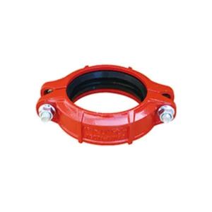 Rigid Coupling Rigid Coupling | XGQT 1 | 1" to 12" | 12 |
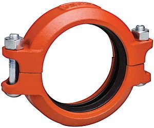 Flexible Coupling Flexible Coupling | XGQT 2 | 1" to 12" | 12 |
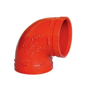 Elbow 90 Deg. Elbow 90 Deg. | XGQT 01 | 1" to 12" | 12 |
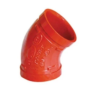 Elbow 45 Deg. Elbow 45 Deg. | XGQT 02 | 1" to 10" | 11 |
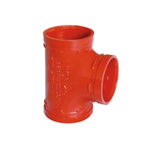 Equal Tee Equal Tee | XGQT 03 | 1" to 12" | 12 |
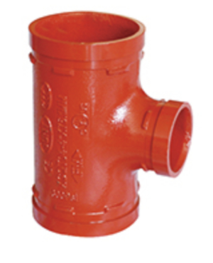 Reducing Tee — Grooved Outlet Reducing Tee — Grooved Outlet | XGQT 04 | 2-1/2" to 12" | 23 |
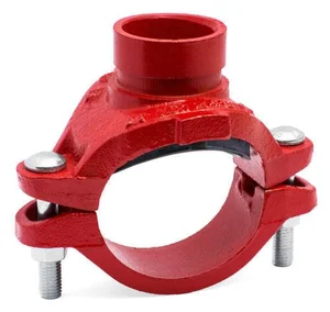 Mechanical Tee — Grooved Outlet Mechanical Tee — Grooved Outlet | XGQT 3 | 2" to 8" | 31 |
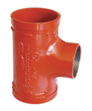 Mechanical Tee — Threaded Outlet Mechanical Tee — Threaded Outlet | XGQT 3S | 2" to 8" | 29 |
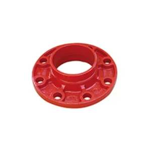 Adaptor Flange Adaptor Flange | XGQT 08 | 2" to 12" | 9 |
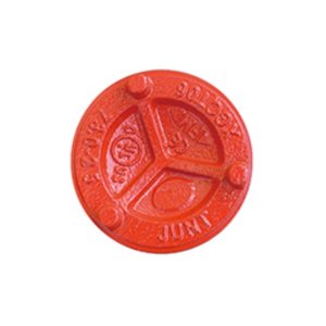 End Cap End Cap | XGQT 06 | 1" to 12" | 12 |
Gaskets. Specify EPDM for fire water service. It covers −34 to +150 °C, is UL classified for potable water, and is the standard compound supplied. Nitrile is for petroleum service and must not be used on water systems; the full selection table is on the dimensions page.
Frequently asked questions
Are grooved fittings accepted for fire NOC projects in India?
Yes, provided the fittings carry the approvals the consultant has specified. The Sant grooved range is UL Listed and FM Approved, which is what is normally called for on sprinkler and hydrant work designed to NFPA 13 or to local fire authority conditions. Keep the approval documentation with the submission, and the marks are cast into the fittings for the site inspection.
What is the difference between UL Listed and FM Approved?
UL Listed means Underwriters Laboratories has tested the product against its published standard and audits the factory so production continues to match. FM Approved means FM Approvals has tested it for use in a property it would insure, which puts more weight on performance under fire and pressure conditions. Specifications commonly ask for both.
What is the maximum working pressure?
The maximum working pressure is 2.5 MPa. On the published range, couplings and tees are rated 300 PSI (2.07 MPa) up to 6 inch and 232 PSI (1.60 MPa) from 8 inch to 12 inch; elbows carry 300 PSI across the full size range. Test pressure is 12.5 MPa.
Can grooved fittings be used on hydrant lines?
Yes. Hydrant risers and ring mains are a standard grooved application. Use rigid couplings up the riser so it behaves as a braced line, flexible couplings at floor take-offs and around the pump set, and flange adaptors to land the riser into valves and headers.
How fast can you supply a project BOQ?
Send the bill of quantities on WhatsApp at 9999889008 or to sales@vijaysalescorp.com and a priced quotation comes back the same working day in nearly every case. Moving sizes are ready stock in Delhi; where a line has to be called from the factory, allow one to two weeks from a firm order.
Pricing a fire fighting package?
Send the BOQ in any format — a marked-up drawing, a spreadsheet or a typed list. It comes back priced line by line with the stock position.